Professional manufacturer of vertical & horizontal wind turbine generator, PMG generator
info@engelec.cn
- All
- Product Name
- Product Keyword
- Product Model
- Product Summary
- Product Description
- Multi Field Search
Views: 225 Author: Site Editor Publish Time: 2020-01-11 Origin: Site
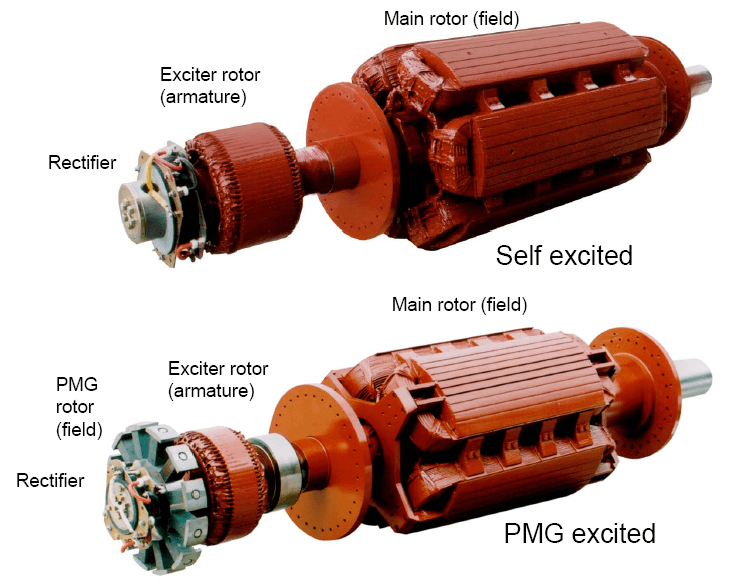
Main Rotor of Permanent Magnet Generator
The Main Rotor of PMG
• Is a field that induces voltage in the main stator.
• Powered by the exciter rotor.
• Connected to the (+) and (-) rotating rectifier terminals.
• Coils are connected in series around a core.
• Laminated core is typical
•Solid core with large rotors
• Current flow is directed in a clockwise and CCW rotation to create north and south poles.
• Pressed on a shaft.


Types

Layout
Frequency, RPM, Pole #
If you have a prime mover that runs at 1000
RPM and you wanted 50 Hz, you would need a generator with how many poles?
(50 Hz × 120)/1000 RPM= 6 poles

Damper Cage
• Also called “Amortisseur windings.”
• Copper bars through the pole faces and shorted together by the end plates.
• Standard for all but traction generators, solid rotors.
• Has a very short time constant (effect expressed in datasheets as X”d).
• Helps with parallel operation
• Helps with load-induced harmonics (non-linear loads).
• Helps reduce initial voltage dip during motor starting.

Magnetism
Magnetic flux paths (i.e. flow of magnetism) for a generator operating at 0.8 PF

